|
There are currently no product reviews.
 ;
Everything okay, thanks a lot. It was a pleasure for me to make a deal with you.
;
A deal without problems, very fast and the manual is a good quality. Sorry for the my english.
;
Superb service and excellent quality of the document received
;
no problems with the purchase of a circuit diagram
;
Scan are good quality and overall just what i was looking for. Thanks!
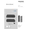
CX-977
Fig. 5: RFRP and RFCT circuit
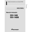
5) SBAD Signal Circuit unit
In this unit, outputs from the photo detector, namely, E and F are processed through the addition amplifier. That is, E and F are added together and (E+F) signal is output from #15 pin of IC101 (TA2153FN), as SBAD signal. This SBAD signal, along with Focus Error signal, is used as one of the conditions that the system uses to internally judge Focus ON/OFF based on them. Also, SBAD signal is used to detect defects: defects that may be detected when the Pickup passes a scratch on the disk, for instance.
Fig. 6: SBAD circuit
5
|