|
|
|
Who's Online
There currently are 5843 guests online. |
|
Categories
|
|
Information
|
|
Featured Product
|
|
|
 |
|
|
There are currently no product reviews.
 ;
Easy to order the manual. Good quality and fast delivery.
;
The Service Manual for Sansui AU-9500 was very helpfull, in complete and in good printable condition.
Thanks.
;
Dear Sir,
Document is original service document of sharp. I had a problem with the door contacts. Fuses where blown. With the manual in a few minuts is was clear what the problem was.
Manual was of great help.
With kind regards,
Martie Verhoeven
The Netherlands.
 ;
The scan is clear and well readable with very few weaker spots, usually on black background with white letters, but with enough zoom those spots can be read.
Printout is clear, the manual is complete and has all pages scanned.
I would give 5 stars, except that it is not in color, and the schematic and PCB pages are scanned on multiple pages. The document is locked (except printing) so the pages can not be extracted to compose them together for printing on the large plotter
It is worth the price tag.
;
let's say first that i do not need to have a credit for my opinion, i am a retired sparkie and i voluteerd to fix an electronic device for a local "Youthgroup",as no diagram was present i checked the "net" and gambled on this site and paying some fee via PayPall, i was gladly surprised that the manual arrived as was stated, GOOD SHOW, and best wishes, John
5
6
7
8
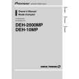
7. DISASSEMBLY
While the photograph shown is slightly different from this model in shape, the disassembly procedure is the same. - Removing the Case (not shown) 1. Remove the Case.
A
-
Removing the CD Mechanism Module (Fig.1)
CD Mechanism Module
1
Remove the four screws.
Disconnect the connector and then remove the CD Mechanism Module.
1
B
1
- Removing the Grille Assy (Fig.1)
2
Release the two latchs and then remove the Grille Assy.
1 2 1 2
C
Grille Assy
- Removing the Tuner Amp Unit (Fig.2)
Fig.1
1 2 3 4
Remove the two screws.
2
Remove the two screws.
2
D
Straighten the tabs at two locations indicated. Remove the two screws and then remove the Tuner Amp Unit.
4 4 1 1
E
3 3
Tuner Amp Unit
Fig.2
F
DEH-2050MP/XN/ES
5 6 7 8
23
|
|
|
> |
|