|
|
|
Who's Online
There currently are 6043 guests online. |
|
Categories
|
|
Information
|
|
Featured Product
|
|
|
 |
|
|
There are currently no product reviews.
 ;
Thank you for your shop manual! Your help was very useful - the device is repaired! Once again - Thank you! I wish you a successful business! Edward (Russia).
;
It was a great experience,instead of purchasing a new Stereo Amplifier ,in just minutes i repaired my old one and that was thaks to the manual I have purchased from you.
Thanks again.
Samuel Alter
;
Das ging ja sehr unkompliziert hat bestens geklappt und die Quallität ist auch noch gut.
Vielen Dank dafür.
;
Everything okay, thanks a lot. It was a pleasure for me to make a deal with you.
;
A deal without problems, very fast and the manual is a good quality. Sorry for the my english.
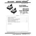
BD-V3000, BD-V3010
AD8323ARU (MAIN ASSY : IC1701)
� UP Stream Amplifier
� Block Diagram
VCC
5,9,10,19,20,23,27
R1
BYP
21
AD8323
15
VOUT+ BUFFER
ATTENUATION CORE
VIN+ DIFF OR SINGLE INPUT AMP POWER AMP
ZOUT DIFF = 75 POWER-DOWN LOGIC
14
VOUT�
VIN�
8 R2
ZIN (SINGLE) = 800 ZIN (DIFF) = 1.6k
DECODE 8 DATA LATCH 8
SHIFT REGISTER
1
DATEN
2
DATA
3
CLK
4,8,11,12,13,16, 6 17,18,22,24,28 PD
GND
7
SLEEP
� Pin Function
PIN FUNCTION DESCRIPTIONS
Pin No. 1
Mnemonic DATEN
Description Data Enable Low Input. This port controls the 8-bit parallel data latch and shift register. A Logic 0-to-1 transition transfers the latched data to the attenuator core (updates the gain) and simultaneously inhibits serial data transfer into the register. A 1-to-0 transition inhibits the data latch (holds the previous gain state) and simultaneously enables the register for serial data load. Serial Data Input. This digital input allows for an 8-bit serial (gain) word to be loaded into the internal register with the MSB (Most Significant Bit) first. Clock Input. The clock port controls the serial attenuator data transfer rate to the 8-bit masterslave register. A Logic 0-to-1 transition latches the data bit and a 1-to-0 transfers the data bit to the slave. This requires the input serial data word to be valid at or before this clock transition. Common External Ground Reference.
2 3
SDATA CLK
4, 8, 11,12, 13, 16, 17, 18, 22, 24, 28 5, 9, 10, 19, 20, 23, 27 6 7 14 15 21 25 26
GND
V CC PD SLEEP OUT� OUT+ BYP V IN+ V IN�
Common Positive External Supply Voltage. A 0.1 F capacitor must decouple each pin. Logic �0� powers down the part. Logic �1� powers up the part. Low Power Sleep Mode. In the Sleep mode, the AD8323�s supply current is reduced to 4 mA. A Logic �0� powers down the part (High Z OUT State) and a Logic �1� powers up the part. Negative Output Signal. Positive Output Signal. Internal Bypass. This pin must be externally ac-coupled (0.1 F cap). Noninverting Input. DC-biased to approximately V CC /2. For single-ended inverting operation, use a 0.1 F decoupling capacitor and a 39.2 resistor between V and ground. IN+ Inverting Input. DC-biased to approximately V CC /2. Should be ac-coupled with a 0.1 F capacitor.
69
|
|
|
> |
|