|
|
|
Who's Online
There currently are 5983 guests online. |
|
Categories
|
|
Information
|
|
Featured Product
|
|
|
 |
|
|
There are currently no product reviews.
 ;
I BOUGHT A PAIR OF INFINITY VINTAGE SPEAKERS THAT REQUIRED TO BE REPAIRED AND THE ELECTRONIC TECHNICIAN ASKED ME FOR THE SERVICE MANUAL.
I TRIED TO GET IT AT THE MANUFACTURER'S SITE WITH NO SUCCESS, SO I STARTED TO LOOK FOR IT IN THE WEB FOR A LONG TIME, UNTIL I FOUND THE SERVICE MANUAL IN THIS EXCELLENT SITE "OWNER'S MANUAL.COM".
NOW I HAVE MY SPEAKERS WORKING AND ENJOYING THE MUSIC I LIKE.
THANKS TO "OWNER`S MANUAL.COM" I RECOMMEND THIS SITE TO EVERYONE.
;
Very quick response. Very good and accurate print quality of the scanned document.
 ;
The service manual was very usable and clear enough to see the individual values of all of the components (unlike some of the service manuals I have gotten in the past from web sites similar to this one). The price was right and the information was greatly appreciated. It helped me with an otherwise very difficult repair. It was much needed and appreciated. A faster turn around on my order would be nice, but I understand the constraints on your staff's time. Thank you for your service.
;
Excellent manual. Helped me out with disassembling and troubleshooting my projector.
;
thanks you are the best.Very good detail, Quick service response. A useful service manual with all details.
5
6
7
8
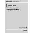
- Removing the Case (Fig.5)
A
1 2 3
Remove the two screws and then remove the Holder. Remove the screw.
3 1 3 2 3 1 3
3
Remove the five screws and then remove the Case.
B
Case
Holder
Fig.5
- Removing the Display Assy (Fig.6)
Motor Unit
1
Remove the screw.
Disconnect the connector and then remove the Motor Unit.
Switch
C
1
2 3
Remove the two screws and then remove the two Holders. Pull out the Display Assy in the arrow indicated direction.
Note) When reassembling, hold the switch down with tweezers or the like and put the Display Assy back to the Chassis. Otherwise, the switch may be damaged and not function properly.
D
2
2
Holder
3
Holder Display Assy
Fig.6
- Removing the Main Unit (Fig.7)
Bracket
2 3 1 3 3
Shaft Unit
2
E
1 2 3
Remove the screw and then remove the Bracket. Remove the four screws and then remove the Shaft Unit. Remove the three screws.
2
2
Disconnect the connector and then remove the Main Unit.
Main Unit
Fig.7
F
AVH-P6500DVD/UC
169 7 8
5
6
|
|
|
> |
|